
Antenna/Tower Page

The
north tower mounts a 2 meter ringo, 7 element 6 meter home brew beam, an 11 element 2 meter beam,
and a 2 element 40 meter beam.
The tower height is 72 ft, with a 2" OD 24 ft mast, extending 17 feet for antenna mounting.
The rotor is a Yeasu G-1000DXA.

This is the start of the south tower. To date this tower has it's first set of guys in
place. It is ready for mast installation. Once the full tower is up, the mast
will be drawn up from the bottom through the thrust bearing on top. Attaching
antennas then raising the mast and adding more antennas etc. This technique
worked out really well on the north tower.

This is the start of the north tower.

With the expert help of Dain, AA7YE, and the ground
crew, the tower went together very well!
I'm putting these next pictures here because I have read about many guys requesting info on this technique. I have read great explanations of how to do it and have done so, but pictures sure help!

With the gin pole in place, time to put in the mast.

The mast is 24 feet long, 2" OD, 1/4" wall,
and HEAVY!!! These specs were calculated for the load and size of antennas, by
means of the MARC program. The tie point is 10 foot from the end. A muffler
clamp was used as the 'stop' for the raise rope. Worked great! Somewhat tough to
see is the tag line attached to the top of the mast. Once the mast is in the
position shown, it is ready to be inverted and dropped down into the
tower.

While the ground crew holds the mast in place, the tag
line is slowly pulled, thus inverting the mast. Many guys prefer to do this
operation after the tower is fully erected, but I preferred to put in the mast
at the 30 foot level versus the 70 foot level. In my case, bringing the mast up
through the bearing then attaching antennas was much easier than lowering the
mast through the bearing then having to re-raise it to attach antennas.


Once the mast is inverted, the ground crew SLOWLY
lowers the mast into the tower until it reaches the ground, but resting on a
wood block thus enabling a rope to be placed through the center for raising
later.
I must admit, I was leery of this installation technique at first, but trusting the guidance of those who are in the know and have the experience, I tried it and it really did work out slick!
I must give credit where due, through
tons of information, ideas and REAL experience obtained from the gents on the Tower Talk
reflector, available for sign up through www.qsl.net,
this project is working out quite well.
A BIG THANKS to all that have
helped with very good info!

This is the fully populated south
tower.
From the top:
Cushcraft 6 mtr Ringo
Cushcraft A3WS, 12/17 mtr beam
Two horizontally stacked 16 element KLM 2 mtr beams
On the above cross boom:
an 11 element
Cushcraft 440 beam
an 11 element converted 2 meter to 220 beam
Hygain TH-6

Raising the first half of the TH-6 was
not too difficult, just had to be good at missing guys! :-)

The second half went up equally well. I
used one guy wire as a tram line and a rope as a temporary tram line.

Finally fully constructed! :-)
In the close up the 160 meter inverted loaded Vee can be seen.
Guying


Since there was a few feet of guy cable longer than
needed, instead of cutting it off, I used it to thread through the turn
buckles.
For those who might need to know the dimensions of the equalizer plates, here
they are! The steel plate is 3/16" thick, galvanized. Click on the pic.


I had to get a little creative with the 'chain to
equalizer plate' connection. The links were too short and too small to connect
directly to the cross bolt, so, a machined steel block was made to accommodate
all dimensions, (3 3/4" x 1 1/2" x 5/8"). Zinc painted to fight
corrosion.
Oh yeah the chain, certainly sized for the load and connected to a 3150 pound 2'
x 2' x 6' construction block, buried under 2+ feet of earth. At $25.00 each, it
was allot less expensive and allot less work than pouring a slab, and much
faster! The back hoe operator just dug the hole, (slot), dropped it in and
covered it up, done! My back felt great just watching it happen! ;-) Total
digging time for all six anchor slots, inserting the blocks, covering them and
digging the two base holes was exactly five hours!


I also made a jig to hold the chain coming out of the ground to the proper angle
for the guys, when being covered up with dirt. This was to reduce as much as
possible the amount of straightening out, that the chain would have to go
through from the guy tension. Worked quite well!
Bases


Here is one of the 4'x4'x4' forms ready for
installation. Once positioned, leveled and secured, I dug out an extra 6"
of dirt from the floor, which was replaced by 6" of 3/4"gravel for
tower drainage. The tower base sits into the gravel approximately 2". The
rebar cage was constructed, sorry no pics, paying attention to Ufer grounding
techniques. Once the base was positioned and secured, fill'er up! Notice in the
far right pic, just left of the tower leg, this is the solid copper 2"
ground strap attached to the rebar cage.
Grounding

This is the splicing technique that I used to mechanically
and electrically bond two pieces of 2" copper strap together. This was necessary
as I chose to obtain the strap material from a local recycler, and of course you
never get the exact length needed. But, I saved allot of money that way! The
'clamp' parts are 1/8" copper and the fasteners are stainless. All
connections were coated with KOPR-SHIELD®, distributed by Thomas & Betts
(CP-16) made by Jet Lube.

This is a typical strap to ground rod
connection. The clamp is made by Polyphaser
# 58R-112S. The ground rod was bought locally and is 9/16" O. D., which
required the addition of shims in order for the clamps to tighten correctly. Not
a problem! I cut a 1/2" copper pipe lengthwise and then cut it to the
length of the clamp. The two halves fit perfectly and after coating all parts
with more kopr-shield, they tightened up very well. Before burying, I covered
the rods with a heavy duty plastic bag, just folded it over, to help reduce
moisture from the wx and sprinklers etc.
So how do you drive an 8 foot ground rod into the ground when it has to be done under a roof that is just over 8 feet high with absolutely no room to swing a sledge or use a post driver???
You get creative!!! Here's how!

Attached to the rod is a home brew clamp, with the rod
shown almost "driven home". Notice the Polyphaser clamp at the bottom.
This is part of the SPG, for the coax prior to shack entry. More on this further
down the page.


I took a piece of angle iron, drilled in some holes and
made some U bolts out of 3/8" threaded rod. I attached the clamp at the
middle of the rod and drove it in with a sledge until it had to be repositioned
as in the above pic. Worked perfect!
This location is next to the shack and will be the secondary single point ground
where I can disconnect all coax lines before they enter, in case of a storm. The
main single point ground is at the base of each tower.


South tower grounding bar, 3/16" x 2" copper bolted to the tower with stainless U
bolts. The flat
bar
that comes with the U bolt, is used to space the copper away from the tower leg. No
galvanic action here!
As a side note, to add grounding radials or other ground connections, you could
use just a stainless u-bolt and attach wires to it with lugs.
As of 10-15-17 I have added the following concerning galvanized steel (tower legs) versus stainless steel clamps/hardware. A gent on the TowerTalk reflector commented that stainless steel against copper and stainless against galvanizing isn't good. This peaked my curiosity because I always read that it's okay. Doing further research was in order. According to the following study, (link), there is some truth to this however, there is one sentence in the report that pretty much "okays" this combination. It is, "The existence of two dissimilar metals in direct contact can be of no problem whatsoever if there is no electrolyte material present". Reading the whole article it's obvious that they are referring to SST and galvanized steel, since this is the subject of the article. My pictures also back up this sentence.
For those who would like the real technical stuff about this, as well as other metal combinations, check this link: http://www.npl.co.uk/upload/pdf/bimetallic_20071105114556.pdf
After approximately 17 years of being clamped together, (as of 10-15-17), I removed one of the u-bolt clamps to inspect if there was any corrosion or 'issues' due to these two dissimilar metals. I found none, zero, nada! Only slight compression marks from being clamped so long. Also the copper was not corroded but is still bright, due to not being exposed to the weather because of the stainless spacer.
To me this proves, as the article states, that if there is no electrolyte present, no destructive action occurs.
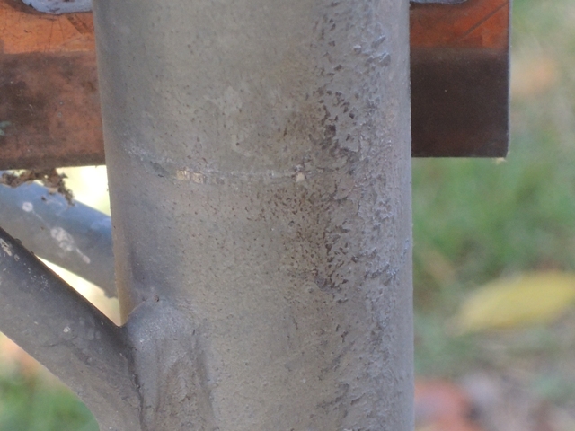 Lateral line mark from the u-bolt compression
 Compression mark of the stainless spacer between the
tower leg and copper bar
Compression mark of the stainless spacer between the
tower leg and copper bar
 Tower leg side of SST spacer, no degradation
 Copper bar side of spacer, no degradation
 Spacer side of the copper bar, no weathering due to the
spacer
Spacer side of the copper bar, no weathering due to the
spacer


Ground strap connection from the tower rebar cage and
two 32 ft long ground straps, incorporating two 8' rods each. Only one of
the 32 footers is shown in the elevated shot. The lateral slot will be for the
PVC tubing, carrying the buried coax. This tubing is the drainage type. It rests
about 12" down on 3" of 3/4" gravel.

North tower grounding bar/coax assembly. Similar
grounding construction as the above tower.


Single point ground, where the coax is connected prior
to shack entry. All are mounted to a 3/16" x 2" x 33" copper bar,
machined to accept the bulk head connectors. These connectors are assembled with
KOPR-SHIELD®, and two stainless internal tooth star washers. The bar is mounted
on two ground rods via another pair of Polyphaser
# 58R-112S clamps, suspended 7" above the ground.
All coax and rotor cables can be quickly disconnected from the outside of the
shack in case of storms. The three which are not connected, (in the second pic),
to cables on both sides of the bar are spare cables routed to the towers.
All connectors are silver/Teflon, screwed onto the coax trapping the braid
between the connector and the outer coax covering, as well as being soldered,
thus providing a mechanical and electrical connection.
Also
incorporated are two pull ropes for future or replacement coax changes.
All coax and rotor control cables are buried approximately 12" underground, in drainage tubing which lays on 3 inches of 3/4" gravel.
Ok, for those who might be wondering, the valve is an RF parasitic regulation valve, oh no wait... it's for shutting off one section of yard sprinklers :-)
Misc


This contraption, actually two were made, is designed
to aid in raising to level, the boom of an antenna, (a TH-6DXX and a 7-2 40
meter beam). The booms are so long and heavy that the manufacturer requires a
mini support guy cable attached to the mast in order to keep them level. The
stock clamp arrangement left allot to be desired so I came up this.
The end with the double ears, is the top where the cables attach. The key is to
make sure that the cables are equal to the center of the beam at the mast. This
way once raised, both ends of the beam are raised equally. The device simply
clamps around the mast, and the remaining hinge pins are installed. The cables
are connected and it is all raised by attaching your gin pole rope to the bottom
ear. Raise it up until the boom is level and simply put a muffler clamp under
the bottom and you're done!
Consider, now you're working lower on the mast, closer to the tower top, and not
having to contend with two clamp parts, two bolts, lock washers and nuts and two
wrenches. Much faster but most importantly, safer!
This was an after thought, it would have been more desirable to have used a solid pipe but I did not have this option as the mast was already installed when I learned how much fun the manufacturers clamping system was! I just had to do something better.
Most recent update 10-15-2017.
Yes the ground crew deserves credit too! Couldn't do it with out them, all of them, and special thanks for the inspirational efforts of Ed, K3ZFF ;-)
![]()